


Behind every vehicle is a CAN bus
CAN lines are robust, efficient, and versatile. Nominal Connect makes them legible.

What is CAN?
This section explains CAN communication, along with an implemented example using a CAN line to read thermocouple data and display it using Nominal Connect. If you are already familiar with CAN bus and want to see how you can use Nominal Connect to intuitively view your data, skip to “Reading and Logging Thermocouple Data using Nominal Connect”
Controller Area Network (CAN) is a twisted-pair wire communication protocol that is widely used in the automotive and machinery industry due to being extremely robust, efficient, and versatile. Its prevalence in control systems make its attributes, advantages, and use cases critical to understand.
Instead of having hundreds of wires running from electronic control units (ECUs) to sensors and other ECUs all throughout the car, CAN allows messages to be both sent and received along a single “information highway” to which every module is connected. This works because every message is sent with a unique identifier: for example, a CAN message ID of 123 might be sending information about the engine temperature while a message with ID 482 might be relaying current front left tire pressure.
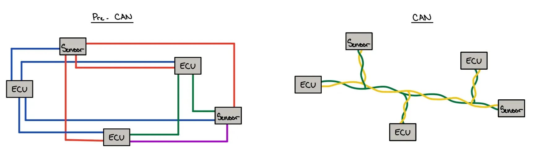
Having everything on a single “information highway” allows for components to be interconnected and listen for the information they need by querying with the IDs. This leads to less cable usage, allowing for weight and cost reductions.
Technical details
The many advantages CAN has over other communication protocols require a technical deep dive to be better understood. These topics include OSI layers, differential signaling, reflection mitigation, and frame composition – all explained below.
OSI layers
The Open Systems Interconnection (OSI) model is a reference model that provides a basis for standards of development in communication systems. There are 7 layers, with complexity increasing along with layer number. The layers also build atop one another, so layer 2 will live above and utilize layer 1. CAN works as a layer 2 communication protocol.
Physical layer (Layer 1)
Layer 1 represents the point-to-point physical medium used to connect two communication nodes. This connection can be copper (electrical signals), fiber optic cable (light signals), or WIFI (RF signals). Layer 1 sets the standards for transmitting and receiving signals such as: voltage level, timing rate, modulation, connectors, and (very important for CAN communication), baud rate, cable length, and termination. For successful communication, both nodes must agree on encoding and decoding.

Once you start dealing with multiple nodes, point-to-point connections get complicated, so it is useful to have a central hub that everything connects to and which can repeat the signal to the other nodes. Anything received at these hubs automatically gets sent to every other port, but this includes errors and collisions. This highlights the largest drawback of utilizing purely layer 1: there is no active signal detection preventing multiple nodes from sending a signal simultaneously which leads to signal corruption. Therefore, Layer 1 networks do not scale well, which is why we build up to layer 2.

Data-Link Layer (Layer 2)
The Data-Link Layer, as mentioned above, runs over Layer 1: a module using Layer 2 will “step down” its information, transmit it along layer 1, and then “step up” to Layer 2 at the receiving end. For simplicity, we can simply abstract Layer 1 away for now. Layer 2, instead of focusing on physical wavelengths, creates frames of information. Devices on Layer 2 also have unique MAC addresses (hexadecimal, not applicable to CAN which uses message IDs) which are assigned to pieces of hardware (have both a manufacturer and specific module component). You can think of a frame as a container for your information, which is divided into the sections shown below:

The improvements that Layer 2 provides over Layer 1 include: collision detection, error handling, and arbitration. Before sending a message, Layer 2 checks to see if there is currently a message on the line, and if so, will wait to send the message until the line is clear. If two signals end up being sent at exactly the same time, the collision detection will jam the signals on all devices which detected the collision and have a randomly set backoff time, after which the collisions will be mitigated. Layer 2 also provides non-destructive bitwise arbitration which helps manage CAN bus access and avoid collisions.
There are standardized CAN bus protocols that establish a common ground between manufacturers, some examples being SAE J1939, ARINC, and UAVCAN.
Differential signaling and reflection Mitigation
CAN communication is extremely resilient to outside noise because it uses differential signaling. Essentially, CAN messages are sent as the difference in voltage between two wires (CAN High: 2.5V-3.5V, CAN Low: 1.5V-2.5V) as opposed to the nominal value of a singular wire. This way, even if electromagnetic disturbance is present, it will affect both signals equally and their difference will thus remain equal. This is also why CAN wires are twisted: if one wire is constantly further from the disturbance it will create unequal disturbance between the wires.

CAN is also resilient against reflections. You can imagine electrical reflections as waves crashing against a wall - the energy from the wave is reflected back into the water which disturbs the incoming waves. This is a problem when dealing with electrical signals, because these reflections will distort and corrupt the signal, leaving the message a garbled mess. By including 120-ohm termination resistors at the nodes, we can implement impedance matching to provide consistent impedance and absorb signal energy. One caveat of using CAN is that you have to ensure that the wires/traces are length-matched so that the data signals obey the hold time requirements of the receiving chip: the data signals must remain within a certain relative timing window to the clock signal. There is also best practice guidance for maximum node length based off of bitrate: (1 Mbit/s: ~25m, 500kbit/s: ~100m, 250kbit/s: ~250m, 125kbit/s: ~500m)

Frame composition
When reading CAN messages, the displayed information will usually be as follows:

However, the standard CAN frame is composed of many other frame fields as shown below:

Where:
SOF: This field indicates the beginning of the frame
ID: This field contains the frame identifier, where lower numbers have higher priority
RTR: Remote Transmission Request describes if a node is a data frame or remote request frame
Control: The control field contains the ID extension bit along with a Data Length Code (DLC) which specifies the length of the Data field
Data: The data field contains the actual meat of the message - sends the payload
CRC: The Cycle Redundancy Check detects errors and ensures data integrity
ACK: The acknowledgement field indicates whether the node has received the data correctly
EOF: This field indicates the end of the frame
Message decoding and endianness
CAN data is not human-interpretable (not by me at least) unless you decode it. To do this, many companies will write their own encoding and decoding schemas (.dbc files) which will often look like this:

Where you can use the following as a dictionary to decode a message:
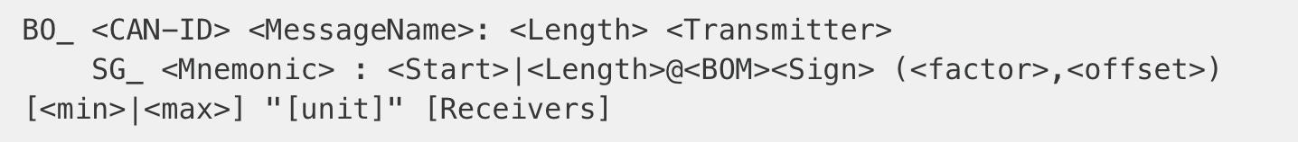
Where:
Mnemonic: Unique Name Identifier
Start: Start bit of the signal
Length: Number of bits in signal
BOM: Endianness → 0 = big, 1 = little
Sign: Signed or Unsigned integers → + = unsigned, - = signed
Factor: Multiplicative scale to decode signal
Offset: Offset used to decode signal
Min: Signal minimum value
Max: Signal maximum value
Unit: Signal units
Lets run through a decoding example using the following CAN message:
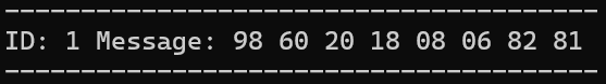
We first convert the message from hex to binary:
NOTE: One important interjection that must be made here is related to endianness. Endianness is a wider computer science concept which defines the order in which a computer stores a sequence of bytes (IMPORTANT: bytes not bits). The .dbc shows that the decoder uses little endianness - the least significant bytes are placed first and most significant bytes are placed last (1 2 3 4 5 → 5 4 3 2 1).
We convert the message to little endian:
Now we can split our message into the splices described in the .dbc - NOTE: we use the big endian indices (so CJ temp running from bits 0:7 means that it will now run from bits -8:-1)

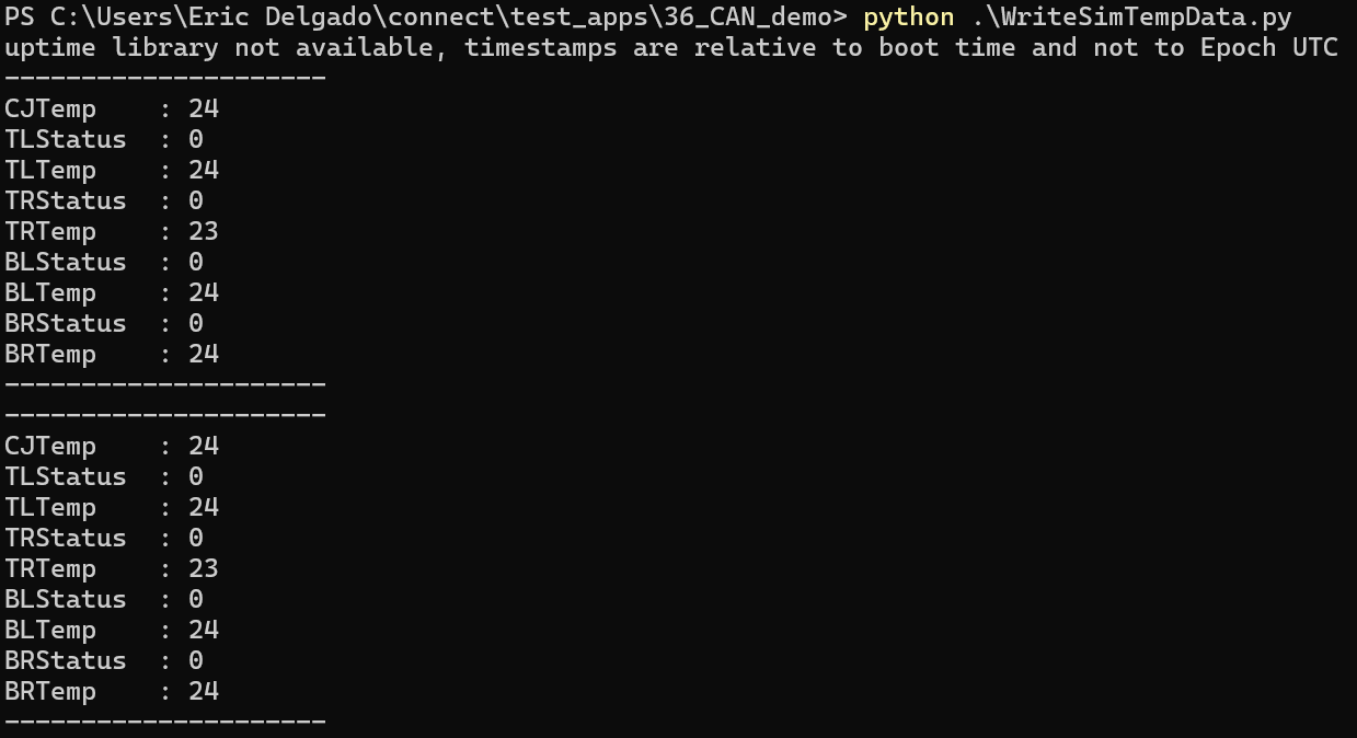
Subsequently we convert from binary to base-10 and apply our scaling factors and offsets to ultimately decode the following from the CAN message:

Because the thermocouples were simply left in ambient air, the end result is quite boring (all temperatures are the same), but we have successfully decoded the CAN message!
Read & log thermocouple data using Nominal Connect
To demonstrate the process of using CAN to read data, we will take temperature data from four thermocouples and stream this to Nominal Connect. For this project we will use:
Nominal Connect
PEAK CAN to USB Adapter (PCAN - UCB)
CANmod.temp: 4x Thermocouple-to-CAN temperature sensor
4 K-type Thermocouples
Arduino UNO MINIMA (used as voltage source)
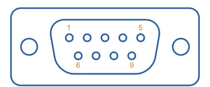
To connect to the D-sub 9-pin connectors on both the PCAN and CANmod, we will attach jumper cables as follows:
Pin 1: 5V - Arduino (source) to CANmod
Pin 2: CAN-H - CANmod to PCAN
Pin 3: GND - Arduino (source) to CANmod
Pin 7: CAN-L. - CANmod to PCAN
We will then connect our PCAN and Arduino USBs into our computer and end up with the following setup:

NOTE: Best practice is to use yellow for CAN-H 🟡 and green for CAN-L 🟢 (industry standard).
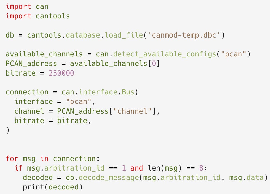
We can then use a python-can import (pip install python-can), read CAN messages from the CANmod module, and decode them using the associated .dbc file.
To easily visualize and log this data, we can use Nominal Connect. Nominal Connect is a real-time testing and automation platform that gives the user the freedom to create custom UIs to clearly visualize their data quickly! Connect also has integrated functionality with Nominal Core, allowing for simple, seamless data transfer and storage for future view and further analysis (to learn more about Nominal Connect, visit here). We can simply build an interface like the one shown below and stream the thermocouple CAN data to Connect.
With Nominal’s product suite, engineers can get real-time visibility into their CAN data, and store that data in Nominal Core’s flexible, queryable data warehouse. This means faster time-to-insight, constant data availability, and accelerated test programs.
References
Mahmoud, Walid. “OSI Model: Layer 2 — The Data Link Layer.” Medium, 28 July 2024, https://walid-mahmoud.medium.com/osi-model-layer-2-the-data-link-layer-c7513c701e81.
“CAN Bus Explained - A Simple Intro [2025].” CSS Electronics, https://www.csselectronics.com/pages/can-bus-simple-intro-tutorial. Accessed 5 June 2025.
“D-Subminiature (D-Sub) Connectors.” Mbedded.Ninja, https://blog.mbedded.ninja/electronics/components/connectors/d-subminiature-d-sub-connectors/. Accessed 5 June 2025.